Some Irinos boxes are available in ‘Master’ and ‘Slave’ versions. They differ only in terms of the communication unit. The measurement unit remains the same in all cases. The following illustration shows this using the Irinos SC-TFV box as an example:
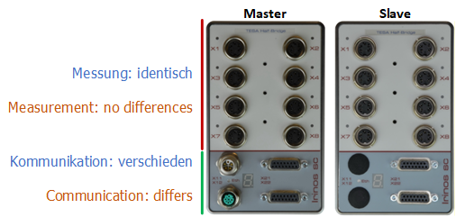
Both versions have a 7-segment display for showing the box and system status.
Normally, the 7-segment display shows the box number of the Irinos box. This is assigned during box addressing. If the box number is a single digit, the following applies: whilst the box number is displayed, the dot on the 7-segment display flashes.
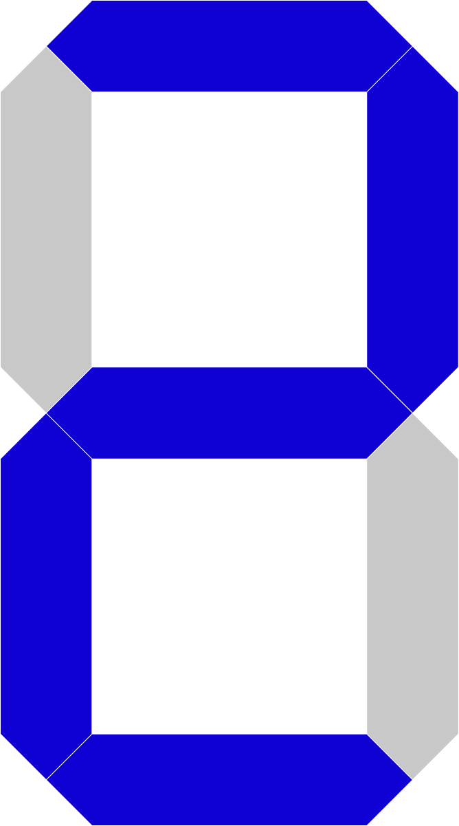
As soon as an event occurs, the letter F followed by the event number is displayed, e.g. F24 for an overload or short circuit in the incremental encoder power supply on the Irinos Box SC-INC. The status can also be read from the PC (see DLL interface). In the event of an overload or short circuit in the SC-TFV’s push-button power supply, the letter sequence “OSC” is displayed.
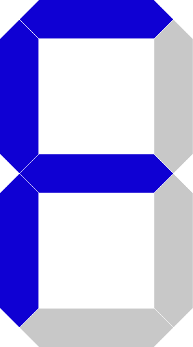
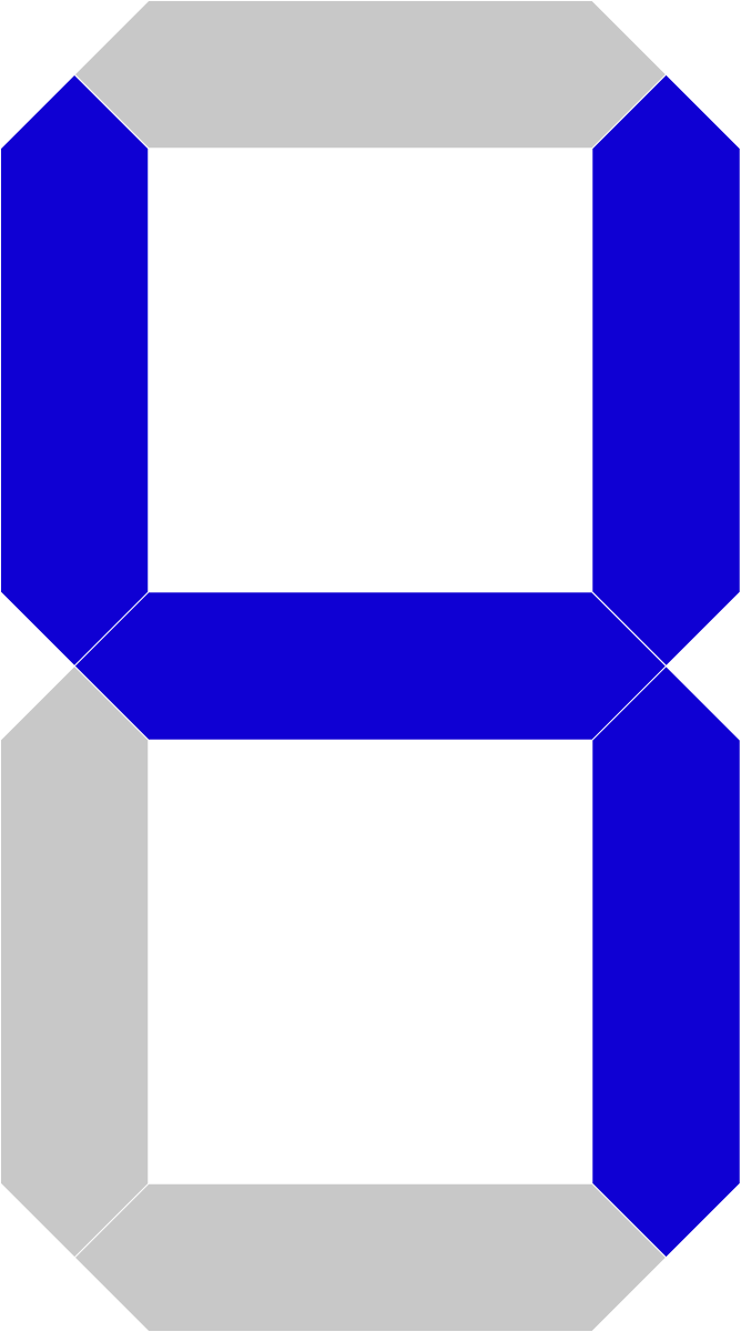
There is one special feature that occurs when the device is switched on: the IP details of the network interface are displayed once on the first Irinos box with a 7-segment display.
If the DHCP server is enabled, only ‘dHCP’ is displayed; otherwise, the IP address and subnet mask are shown.
General connector pinouts
Power supply 24V DC / M12 L-coded
➔ Connector type: M12 5-pin male, L-coded
The M12 L-coded connector is a de facto industry standard for supplying devices with 24V DC. The Irinos system uses the standard pin configuration.
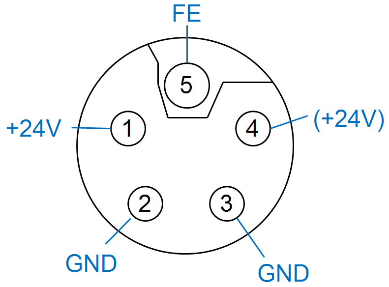
Connectorpinout M12 L-coded
Pin |
Description |
Note |
|---|---|---|
1 |
Us |
+24V DC (Sensor supply) |
2 |
GND |
Ground reference |
3 |
GND |
Ground reference |
4 |
Ua |
(+24V DC Actuator voltage) --> Not used/connected by the Irinos system! |
5 |
FE |
Functional earth |
Power supply Ethernet / M12 D-coded
➔ Connector type: M12 4-pin female, D-coded
The Irinos system’s Ethernet interface is a standard Ethernet interface, such as those found in PCs, for example. It supports a data rate of 100 Mbit/s. This means the Irinos system can be connected to virtually any standard network interface available on the market.
The Irinos system’s Ethernet interface features ‘crossover’ detection. Consequently, it makes no difference whether a standard Ethernet cable or a crossover cable is used.
The Irinos system uses a 4-pin M12 socket (D-coded) as its connector. This is the de facto industry standard for Ethernet.
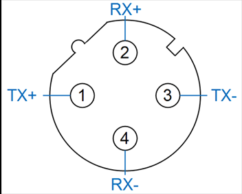
Pin-definition Ethernet interface
Pin |
Description |
Note |
|---|---|---|
1 |
TX+ |
Transmission Data+ |
2 |
TX- |
Transmission Data- |
3 |
RX+ |
Receive Data+ |
4 |
RX- |
Receive Data- |
Connection cable
Suitable connection cables are available from various manufacturers (e.g. Phoenix Contact, Lapp, Murr Elektronik). The connection cable must be Category 5e or higher. Cables from Phoenix Contact have the advantage that they support the ‘SpeedConn’ locking mechanism. This enables the M12 connector to be locked into place quickly. These cables can be ordered under the product group IR-CETH.
The opposite end is usually an RJ45 plug. If required, cables with a second M12 connector or other industrial connectors are also available.
|
Although the Ethernet interface is identical in terms of signalling to real-time interfaces such as ProfiNet, EtherCAT or Sercos, it is not compatible with their real-time extensions. |

Ethernet status / LEDs
The Ethernet status is displayed next to the Ethernet socket:
The ‘Ethernet Link’ LED lights up when an Ethernet connection is active. As soon as data is being transferred, this LED flashes.
SC-Link - Interface / DSUB15F
➔ Connector type: DSUB 15-pin female
The SC-Link interface combines power supply and communication cables between the Irinos boxes into a single cable/connector. A high-quality SC-Link connection with specific electrical properties is therefore required to ensure trouble-free operation of the Irinos system. You should therefore only use the appropriate IR-ILINK cables.
A 15-pin D-sub socket is used as the connector. When used with the appropriate mating plug, this enables IP65 protection to be achieved. The ILink cable is therefore available in a standard version and an IP65 version.
The power supply is fed via the SC-Link interface (see illustration). No wires must be connected to any of the other pins on the SC-Link connector, as this may otherwise cause disruptive reflections.
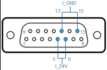
Pinout power supply via SC-Link interface
Pin |
Description |
Note |
|---|---|---|
1 |
IL_Data1 |
Data line 1 |
2 |
IL_GND |
Reference ground for data lines |
3 |
IL_Data2 |
Data line 2 |
4 |
- |
|
5 |
I_24V |
24 V – Power supply for the Irinos system. |
6 |
I_24V |
24 V – Power supply for the Irinos system. |
7 |
IL_Data3 |
Data line 3 |
8 |
IStat |
Detection signal |
9 |
IL_Data4 |
Data line 4 |
10 |
- |
|
11 |
IL_Data5 |
Data line 5 |
12 |
- |
|
13 |
I_GND |
Reference ground for the Irinos system’s power supply. |
14 |
IL_Data6 |
Data line 6 |
15 |
I_GND |
Reference ground for the Irinos system’s power supply. |
Case |
FE |
Shield / Functional earth |
To comply with the applicable EMC standards, the connector housing must be connected to the functional earth (FE). In the case of the IR-PU power supply unit, this is achieved by connecting the connector housing to the protective earth (PE) of the mains cable.
Please note that, with the exception of the IR-PU power supply unit, all Irinos boxes must only be supplied with protective low voltage. For this reason, ‘only’ a functional earth (FE) is required, and not a protective earth (PE).
The pin configuration of the SC-Link connector is designed so that 1Vss / TTL incremental encoders with the standard Heidenhain pin configuration are not damaged if they are accidentally plugged into the socket of the SC-Link interface. This may not be the case for specialised encoders with a different pin configuration.
Communication via the SC-Link interface is based on a bus system which must be terminated at both ends by a terminating resistor. This termination takes place automatically: the Irinos system detects the first and last Irinos box, in which the termination is activated.
An exception to this are the Irinos power supplies of the IR-PU-HWS type. If a power supply is located at the start or end of the SC-Link cabling, the cable length to the next Irinos box must not exceed 0.3 m.