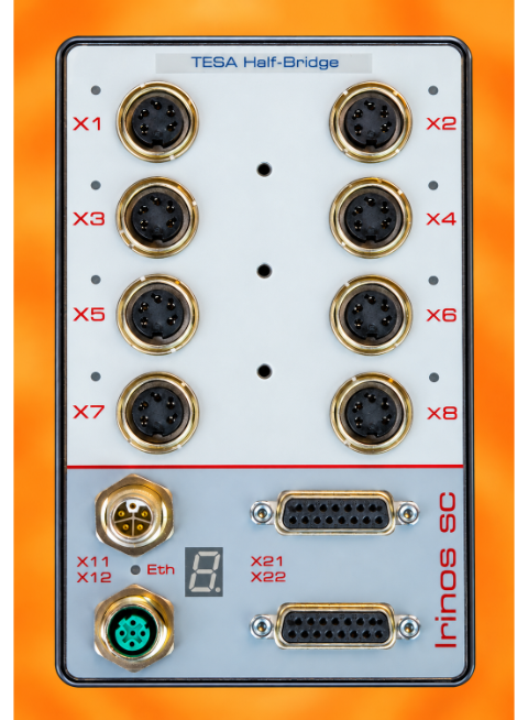
The Irinos Box SC-TFV is suitable for connecting 8 inductive probes. Each Irinos Box is optimised for a specific type of probe. The supported probe type can be identified from the labelling on the front panel.
Alternatively, each input can also be individually configured to measure analogue signals of ±10 V DC (not available for Mahr/Feinprüf).
The configuration of each channel is indicated by an LED next to it:
oGreen LED -> Probe input
oOrange LED -> Analogue input ±10V
Switching between the probe input and the analogue input is carried out via the relevant DLL interface.
With the NmxDLL, the switch to analogue input is performed via NMX_ChannelSetConfig_1, e.g.:
char acStrTx[] = "#AIN10D;1#";
NMX_ChannelSetConfig_1(pHandleNmx, 2, acStrTx, strlen(acStrTx), acStrRx, sizeof(acStrRx), &ulRxSize);
And, conversely, switching to the inductive probe:
char acStrTx[] = "#PROBE;1#";
NMX_ChannelSetConfig_1(pHandleNmx, 2, acStrTx, strlen(acStrTx), acStrRx, sizeof(acStrRx), &ulRxSize);
With the MscDLL, the switch to analogue input is performed using opcode 0x09 and the MSC_WriteCommand function:
pSndBuffer = „#T8;AIN10D;1#“; // Beispiel für Taster 8 à T8 an Taster anpassen
MSC_WriteCommand(pHandle, 0x09, SndBufferSize, pSndBuffer, RcvBufferSize, pRcvBuffer, pBytesReceived, Timeout);
And, conversely, switching to the inductive probe:
pSndBuffer = „#T8;PROBE;1#“;
MSC_WriteCommand(pHandle, 0x09, SndBufferSize, pSndBuffer, RcvBufferSize, pRcvBuffer, pBytesReceived, Timeout);
Probe supply / Sine oscillator
Inductive probes require a sine excitation signal as their supply signal. This is generated by a sine oscillator in the Irinos box. All measurement inputs on an Irinos box share a common sine oscillator. To ensure a particularly accurate measurement result, the signal is generated in such a way that it is virtually free of DC components.
In the event of an overload or a short circuit in the sine wave excitation signal – e.g. due to a faulty probe – the sine oscillator is automatically switched off and this event is reported in the following ways:
oThe text ‘OSC’ is displayed on the 7-segment display.
oVia the measurement value manipulation or via the hardware status readable by the measurement computer software.
The Irinos Box periodically checks whether the short circuit has been rectified. If so, the oscillator restarts automatically.
Measurement
All measurement inputs are sampled synchronously (no multiplexing). The measurement method takes the complete measurement signal into account (i.e. integrative measurement). Compared with the commonly used 1-point or 2-point sampling, this method has the advantage of being much less susceptible to interference. The analogue filter used in this measurement method is designed to suit the mechanical properties of the respective probe.
For technical reasons, different input channels never produce exactly the same measured value for an identical input signal. To enable the input channel to be changed or the Irinos box to be swapped without any problems, the measurement inputs are therefore digitally pre-calibrated at the factory. The calibration is carried out in such a way that the measured value is -32,000 at maximum negative nominal stroke, 0 at the centre of the probe, and +32,000 at maximum positive nominal stroke.
Digital value |
Stroke with Tesa Halfbridge GT21 |
Stroke with Tesa Halfbridge GT61 |
Stroke with Solartron AX/1/S |
Stroke with Mahr 1301 |
Analogue Input |
|---|---|---|---|---|---|
- 32.000 |
- 2000 µm |
- 5000 µm |
- 1000 µm |
- 1000µm |
-10V |
0 |
0 µm |
0 µm |
0 µm |
0µm |
0V |
+32.000 |
+ 2000 µm |
+ 5000 µm |
+ 1000 µm |
+ 1000µm |
+10V |
Please also bear in mind the specific aspects of the manipulation of measured values.
Connector pinouts
➔ Connector type M16 5-pin 270° female
One inductive probe can be connected to each connector. The pin configuration complies with the standard for the respective probe.
TESA Halfbridge
Pin |
Description |
Note |
Used with probe |
Used with analogue input |
|---|---|---|---|---|
1 |
PHASE1 |
Together with PHASE2, it forms the sine wave supply signal (sine wave oscillator) |
Yes |
No |
2 |
GND |
Ground reference |
Yes |
Yes |
3 |
MT_IN |
Measurement input (Probe signal) |
Yes |
No |
4 |
AIN |
Analogue Input ±10V |
No |
Yes |
5 |
PHASE2 |
Together with PHASE1, it forms the sine wave supply signal (sine wave oscillator) |
Yes |
No |
Solartron LVDT
Pin |
Description |
Note |
Used with probe |
Used with analogue input |
|---|---|---|---|---|
1 |
PHASE1 |
Together with PHASE2, it forms the sine wave supply signal (sine wave oscillator) |
Yes |
No |
2 |
PHASE2 |
Together with PHASE1, it forms the sine wave supply signal (sine wave oscillator) |
Yes |
No |
3 |
AIN |
Analogue Input ±10V |
No |
Yes |
4 |
MT_IN |
Measurement input (Probe signal) |
Yes |
No |
5 |
GND |
Ground reference |
Yes |
Yes |
Feinprüf / Mahr
Pin |
Description |
Note |
Used with probe |
No analogue input available |
|---|---|---|---|---|
1 |
PHASE1 |
Together with PHASE2, it forms the sine wave supply signal (sine wave oscillator) |
Yes |
|
2 |
MT_IN_I |
Measurement input Current (Probe signal) |
Entweder MT_IN_I oder MT_IN_U. |
|
3 |
MT_IN_U |
Measurement input Voltage (Probe signal) |
Entweder MT_IN_I oder MT_IN_U. |
|
4 |
GND |
Ground reference |
Yes |
|
5 |
PHASE2 |
Together with PHASE1, it forms the sine wave supply signal (sine wave oscillator) |
Yes |
|