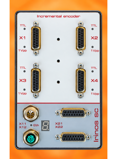
--> It is essential that you follow the application instructions for incremental encoders.
The Irinos Box SC-INC is suitable for connecting 4 incremental encoders.
Each input can be configured via software for either 1Vpp incremental encoders or TTL / RS422 incremental encoders. The current input configuration is indicated by LEDs next to the connector. The configuration can be changed in the following ways:
oVia the Irinos Tool. Please refer to the Irinos Tool user manual for further details.
oVia a configuration command in the measurement computer software.
Depending on the variant, the inputs are preconfigured at the factory for either 1Vpp or TTL/RS422.
Switching between 1Vpp and TTL/RS422 is carried out via the DLL interface.
With the NmxDLL, the switch to 1Vpp is performed via NMX_ChannelSetConfig_1, e.g.:
char acStrTx[] = "#1VSS;1#";
NMX_ChannelSetConfig_1(pHandleNmx, 2, acStrTx, strlen(acStrTx), acStrRx, sizeof(acStrRx), &ulRxSize);
And conversely, switching to TTL with quad evaluation:
char acStrTx[] = "#TTL4X;1#";
NMX_ChannelSetConfig_1(pHandleNmx, 2, acStrTx, strlen(acStrTx), acStrRx, sizeof(acStrRx), &ulRxSize);
Or to TTL with 1-fold evaluation:
char acStrTx[] = "#TTL;1#";
NMX_ChannelSetConfig_1(pHandleNmx, 2, acStrTx, strlen(acStrTx), acStrRx, sizeof(acStrRx), &ulRxSize);
With the MscDLL, the switch to 1Vpp is performed using opcode 0x09 and the MSC_WriteCommand function:
pSndBuffer = „#T8;1VSS;1#“; // Example for probe 8 à Adapt T8 to your probe number
MSC_WriteCommand(pHandle, 0x09, SndBufferSize, pSndBuffer, RcvBufferSize, pRcvBuffer, pBytesReceived, Timeout);
And conversely, switching to TTL with quad evaluation:
pSndBuffer = „#T8;TTL4X;1#“;
MSC_WriteCommand(pHandle, 0x09, SndBufferSize, pSndBuffer, RcvBufferSize, pRcvBuffer, pBytesReceived, Timeout);
Or to TTL with 1-fold evaluation:
pSndBuffer = „#T8;TTL;1#“;
MSC_WriteCommand(pHandle, 0x09, SndBufferSize, pSndBuffer, RcvBufferSize, pRcvBuffer, pBytesReceived, Timeout);
Incremental input LEDs
The LEDs on the incremental input have the following meanings:
LED State |
Description |
|---|---|
Blue on |
Configured for 1Vpp. Normal operation. |
Blue blinking |
Configured for 1Vpp. An incremental encoder error has occurred. |
Yellow on |
Configured for TTL / RS422 with 1x evaluation. |
Yellow long on, short off |
Configured for TTL / RS422 with 4x evaluation. |
Green short on |
The reference mark has been passed. |
Power supply
The incremental encoders are powered by a common 5V supply. This is designed to ensure that sufficient power reserves remain when using most incremental encoders. Please refer to the data sheet for details of the power supply requirements.
The power supply is protected against overload and short circuits on a per-channel basis. If an overload occurs, the power supply to the affected input channel is immediately switched off and this is reported as an error. As soon as the short circuit has been rectified, the power supply is automatically reactivated.
A fault in the power supply can be identified as follows:
oThe ‘F24’ event is triggered and on the 7-segment display, the event message ‘F24’ appears.
oThe corresponding bit in the hardware status of the affected measurement channel is set. This can be read out by the measurement computer software.
Measurement
The incremental encoder inputs are sampled synchronously internally. It makes no difference whether an incremental encoder is configured for 1Vpp or for TTL / RS422.
Fault monitoring
Inputs configured for the 1Vpp incremental encoder type feature channel-by-channel error monitoring of the input signals. If everything is OK, the incremental encoder LED lights up blue continuously; otherwise, it flashes. In addition, errors can be detected in the following ways:
oThe corresponding bits in the hardware status of the affected measurement channel are set. These can be read out by the measurement computer software.
oThe ‘F25’ event is triggered. Its display on the 7-segment display is disabled by default. However, the event is logged in the diagnostic memory.
In the event of an incremental encoder fault, a position value is still output. This may be valid, but not necessarily so. To ensure reliable operation of the measurement system, the measurement computer software must therefore always query and evaluate the hardware status and respond in accordance with the application’s requirements!
Connector pinout
➔Connector type DSUB 15-pin, female
To achieve protection class IP65, suitable D-sub housings are required for the connector.
|
The same connector is used for the SC-Link interface as for the incremental encoder inputs. The pin configuration of the SC-Link connector is designed so that 1Vpp / TTL incremental encoders with the standard Heidenhain pin configuration are not damaged if they are accidentally plugged into the SC-Link interface socket. This may not be the case for specialised encoders with a different pin configuration. You should therefore only ever connect incremental encoders to the input sockets intended for that purpose. |

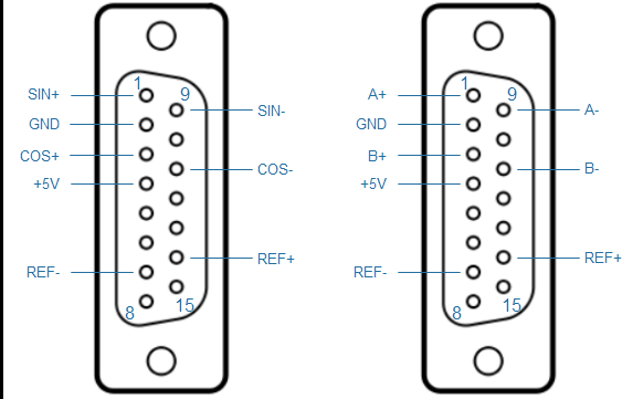
Pin assignment for incremental encoder input 1Vpp or TTL / RS422
Pin |
Description 1Vpp |
Description TTL |
Note |
|---|---|---|---|
1 |
SIN+ |
A+ |
1Vpp: Sine positive signal TTL / RS422: positive 'A'-signal |
2 |
GND |
GND |
Ground reference |
3 |
COS+ |
B+ |
1Vpp: Cosine positive signal TTL / RS422: positive 'B'-signal |
4 |
+5V |
+5V |
+5V power supply for incremental encoder |
5 |
- |
- |
Unused On this pin, the SC-Link interface uses +24V. |
6 |
- |
- |
Unused On this pin, the SC-Link interface uses +24V. |
7 |
REF- |
REF- |
Reference negative signal |
8 |
- |
- |
|
9 |
SIN- |
A- |
1Vpp: Sine negative signal TTL / RS422: negative 'A'-signal |
10 |
- |
- |
|
11 |
COS- |
B- |
1Vss: Cosine negative signal TTL / RS422: negative 'B'-signal |
12 |
- |
- |
|
13 |
- |
- |
Unused On the SC-Link interface, this pin is used as ground reference. |
14 |
REF+ |
REF+ |
Reference positive signal |
15 |
- |
- |
Unused On the SC-Link interface, this pin is used as ground reference. |