
Irinos Measurement System
--> Please read the application notes for incremental encoders.
4 incremental encoders can be connected to the Irinos-Box IR-INC.
Each input channel can be set either to 1Vpp or to TTL / RS422. The current input configuration is displayed via LEDs next to the connector. Changing the input type can be done via the Irinos-Tool or via a configuration string by the measurement software.
Depending on the order number, all channels are either set to 1Vpp or TTL/RS422 as factory defaults.
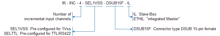
The definition of the type string is as follows:

Connectors for "IR-INC"
Connectors / elements
o4 connectors for incremental encoders
oAn explanation of the communication section can be found in the general overview.
|
The same connector type is used for the ILink interface and the incremental encoders. The pinning of the ILink connector has been chosen to avoid any damage of incremental encoders with standard pinning, if they are plugged into the ILink interface. For encoders with special pinning, this may be different. Only use the appropriate connectors for the incremental encoders. |

LED |
Status |
|---|---|
Blue on |
Configure for 1Vpp. No error detected. |
Blue, flashing |
Configured for 1Vpp. An error has occured. |
Yellow on |
Configured for TTL / RS422. |
Power supply
The incremental encoders have a shared 5V power supply. It is designed to provide enough power reserves for all typical applications. Details can be found in the datasheet.
Each channel has its own overload and short circuit protection. If an overload occurs, the power supply of the respective channel is immediately turned off and an error is signalled. As soon as the short circuit has been removed, the power supply is automatically turned on.
An additional protection ensures that the total load is not exceeded. If an overload of the total output power occurs, the power supply for all channels is turned off and an error is signalled. After removing this error, the Irinos system must be restarted.
A power supply error is signalled as follows:
oThe Event „F24“ becomes active. Irinos-Boxes with 7-digit display (Slave) show the event "F24".
oFor Irinos-Boxes with a status LED (integrated Master), the LED is turned on permanently.
oThe corresponding hardware status bit of the respective measurement channel is set. It can be read out by the measurement software.
Data acquisition
All channels are sampled synchronously. It does not matter, whether the input channel is configured for 1Vpp or TTL / RS422.
Error detection
Channels, which are configured for the input type 1Vpp, have a channel-wise error detection of the input signals. If everything is ok, the blue LED is turned on, otherwise it flashes. In parallel, errors can be detected via the following ways:
oThe corresponding bit in the hardware status of the measurement channel are set. It can be read out by the measurement software.
oThe event "F25" becomes active. Using the standard settings, it is not displayed on the 7-digit display. However, it will be recorded in the diagnostic memory.
If an error occurs, the position value still can be read out. It may be valid, but this is not necessarily the case. For a reliable operation of the measurement application, it is required to read the hardware status by the measurement software. In case it contains an error information, appropriate action regarding the application has to be taken.
