Irinos Measurement System
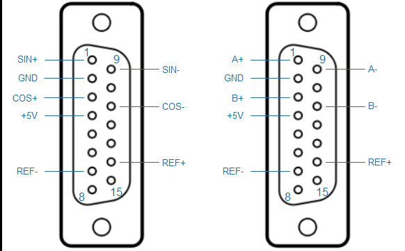
➔Connector type DSUB 15-pin, female
In order to fulfill the requirements of the protection class IP65, an IP65 DSUB connector housing from FCT / Molex is required (type FWA2GA).
|
The same connector type is used for the ILink interface and the incremental encoders. The pinning of the ILink connector has been chosen to avoid any damage of incremental encoders with standard pinning, if they are plugged into the ILink interface. For encoders with special pinning, this may be different. Only use the appropriate connectors for the incremental encoders. |

Connector for incremental encoder 1Vpp or TTL / RS422
Pin |
Description 1Vpp |
Description TTL |
Note |
|---|---|---|---|
1 |
SIN+ |
A+ |
1Vpp: Sine positive TTL/RS422: A signal positive |
2 |
GND |
GND |
Ground |
3 |
COS+ |
B+ |
1Vpp: Cosine positive TTL/RS422: B signal positive |
4 |
+5V |
+5V |
+5V supply for incremental encoder |
5 |
- |
- |
Not used. (At the ILink-Interface this pin is connected to +24V.) |
6 |
- |
- |
Not used. (At the ILink-Interface this pin is connected to +24V.) |
7 |
REF- |
REF- |
Reference signal, negative |
8 |
- |
- |
|
9 |
SIN- |
A- |
1Vpp: Sine negative TTL/RS422: A signal negative |
10 |
- |
- |
|
11 |
COS- |
B- |
1Vpp: Cosine negative TTL/RS422: B signal negative |
12 |
- |
- |
|
13 |
- |
- |
Not used. (At the ILink-Interface this pin is connected to power GND.) |
14 |
REF+ |
REF+ |
Reference signal, positive |
15 |
- |
- |
Not used. (At the ILink-Interface this pin is connected to power GND.) |

