Irinos Measurement System
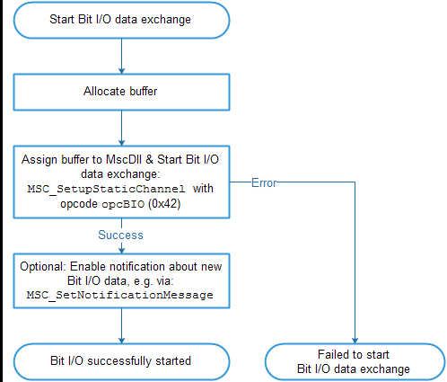
The exchange of Bit I/O data is similar to the static measurement. The following figure shows the steps for the start of the Bit I/O data exchange:

Steps for "starting Bit I/O data exchange"
oThe function MSC_SetupStaticChannel together with the opcode opcBIO (0x42) starts the continuous exchange of Bit I/O data through the MscDll.
Two buffers must be provided:
-A receive buffer, which contains the current output data, followed by the input data received.
-A send buffer, which contains the output data, that shall be send to the Irinos-System.
oAfter calling the function MSC_SetNotificationMessage (alternativ MSC_SetNotificationEvent or MSC_SetNotificationCallback) together with the opcode opcBIO (0x42), the application is informed every time new Bit-I/O data is available. It is up to the application whether it uses or ignores this data.
Using notifications is recommended, but not required.
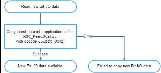
oThe received Bit-I/O data is first stored in an internal buffer of the MscDll. In order to copy them into the buffer of the application, the function MSC_ReadStatic together with the opcode opcBIO (0x42) must be called (see following figure). This function must be called every time new Bit-I/O data has been received.

Steps for "copying bit I/O data into the buffer of the application"
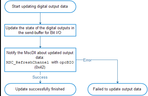
Writing output data to the MscDll
Compared to reading static measurement values, the Bit-I/O data exchange is enhanced by writing data to the Irinos-System. New output data can be written into the send buffer anytime. After each update, the function MSC_RefreshChannel together with the opcode opcBIO (0x42) must be called in order to inform the MscDll about the update:

Steps for "updating Bit-I/O data"
Bit assignment
The number of digital in- and outputs is rounded up to a multiple of 8 per Irinos-Box. Examples:
oAn Irinos-Box has 2 digital inputs. 6 "virtual" inputs are added, the sum is 8 bits.
All virtual inputs are always low.
oAn Irinos-Box has 68 digital in- and outputs. 4 „virtual“ digital in and outputs are added. The sum is 72 in- and outputs.
The bit order depends on the order of the Irinos-Boxes (according to the Box addresses). Two examples are provided in the following tables:
Box type |
Number of digital inputs |
Input bits |
Number of digital outputs |
Output bits |
|---|---|---|---|---|
68 |
1 .. 68 [69 .. 72 -> "virtual"] |
68 |
1 .. 68 [69 .. 72 -> "virtual"] |
|
0 |
- |
0 |
- |
|
0 |
- |
0 |
- |
|
IR-DIO-16-16 |
16 |
73 .. 80 |
16 |
73 .. 80 |
IR-DIO-16-16 |
16 |
81 .. 96 |
16 |
81 .. 96 |
Box type |
Number of digital inputs |
Input bits |
Number of digital outputs |
Output bits |
|---|---|---|---|---|
IR-TFV |
2 |
1 .. 2 [3 .. 8 -> "virtual"] |
0 |
- |
0 |
- |
0 |
- |
|
IR-DIO-16-16 |
16 |
9 .. 24 |
16 |
1 .. 16 |
0 |
- |
0 |
- |
|
40 |
25 .. 64 |
40 |
17 .. 56 |
Update-Rate
The update-rate is identical to the update-rate for static measurement values.
An exception are the digital in- and outputs, which are connected via the IO-Bus to the Irinos-Box IR-MASTER. These are updated about 30 times/s.
Please note:
|
Bit-I/O data exchange is not done in realtime. Always use a handshake-method for the exchange of status information via Bit-I/O. |
Send- / receive- buffer
The size of the send- and receive buffers depends on the maximum number of in- and output bits, which shall be used. A basic rule is, that always the same amount of input bits is read as output bits are written.
If for example 64 output bits are written, then 64 input bits will be read.
If for example 128 output bits are written, then 128 input bits will be read.
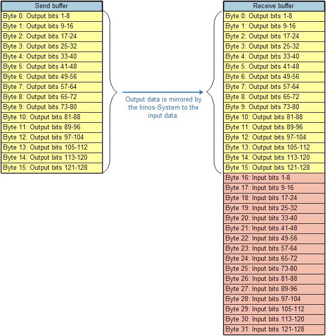
For Irinos-Systems without fieldbus-interfaces like ProfiNet, 128 bits = 16 bytes are sufficient. In this case the size of the send buffer must be 16 bytes.
The receive buffer first contains a copy of the digital output bits. These are followed by the digital input bits. Thus the receive buffer must always have twice the size of the send buffer. If for example 128 bits are used, the size of the receive buffer must be 32. The following figure provides an example:

Bit I/O send- and receive- buffer (example for 128 Bits)

