
Irinos Measurement System
The Irinos IR-HMI1 is a universal control panel for the Irinos measurement systems. All elements are directly accessible via Bit I/O, similar to an I/O Box with 40 in- and outputs.
The definition of the type string is as follows:
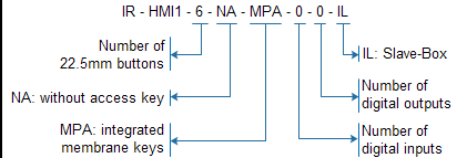
The control panel provides the following control elements:
o6 pcs. push buttons 22.5mm with user-definable functionality, each equipped with a LED for individual illumination, printable lables available.
oSelection of machine number (1-99) via numeric display and +- keys.
oSelection of testplan number (1-99) via numeric display and +- keys.
o7 membrane keys with user-definable functionality: 4 arrows + ESC + # + OK
The control panel is connected to the Irinos system via the ILink interface. Power is also supplied via ILink.

Übersicht der Bedienelemente
The bit assignment is as follows:
Bit-No. |
Input (Irinos -> PC) |
Output (PC -> Irinos |
|---|---|---|
0 |
Push button 1 (upper left) |
LED for push button 1 |
1 |
Push button 2 (upper middle) |
LED for push button 2 |
2 |
Push button 3 (upper right) |
LED for push button 3 |
3 |
Push button 4 (lower left) |
LED for push button 4 |
4 |
Push button 5 (lower middle) |
LED for push button 5 |
5 |
Push button 6 (lower right) |
LED for push button 6 |
6 |
- |
Reserved |
7 |
- |
Reserved |
|
||
8 |
Key "arrow left" |
Preset value for Testplan No. |
9 |
Key "arrow right" |
Preset value for Testplan No. |
10 |
Key "arrow up" |
Preset value for Testplan No. |
11 |
Key "arrow down" |
Preset value for Testplan No. |
12 |
Key "ESC" |
Preset value for Testplan No. |
13 |
Key "#" |
Preset value for Testplan No. |
14 |
Key "OK" |
Preset value for Testplan No. |
15 |
- |
Latch preset value for Testplan No. |
|
||
16 |
Reserved |
Preset value for Machine No. |
17 |
Reserved |
Preset value for Machine No. |
18 |
Reserved |
Preset value for Machine No. |
19 |
Reserved |
Preset value for Machine No. |
20 |
Reserved |
Preset value for Machine No. |
21 |
Reserved |
Preset value for Machine No. |
22 |
- |
Preset value for Machine No. |
23 |
- |
Latch preset value for Machine No. |
|
||
24 |
Current Testplan No. |
Max Testplan No. |
25 |
Current Testplan No. |
Max Testplan No. |
26 |
Current Testplan No. |
Max Testplan No. |
27 |
Current Testplan No. |
Max Testplan No. |
28 |
Current Testplan No. |
Max Testplan No. |
29 |
Current Testplan No. |
Max Testplan No. |
30 |
Current Testplan No. |
Max Testplan No. |
31 |
- |
Lock Testplan selection |
|
||
32 |
Current Machine No. |
Max Machine No. |
33 |
Current Machine No. |
Max Machine No. |
34 |
Current Machine No. |
Max Machine No. |
35 |
Current Machine No. |
Max Machine No. |
36 |
Current Machine No. |
Max Machine No. |
37 |
Current Machine No. |
Max Machine No. |
38 |
Current Machine No. |
Max Machine No. |
39 |
- |
Lock Machine selection |
Presetting the Testplan- / Machine-No.
The Testplan-No. can be preset by the measurement software. First the number must be set by the bits "Preset value for Testplan-No.". A low-to-high transition of the Bit "Latch Preset value for Testplan-No." latches this value as the new Testplan No.
The same applies to the Machine No.
Limiting the Testplan- / Machine-No.
The highest Testplan-No. can be defined by the Bits "Max. Testplan-No.".
If the current Testplan-No. is higher, it will automatically be set to the Max-value.
If the maximum value is 0, limiting the Testplan-No. is inactive.
The same applies to the Machine No.
Lock selection of Testplan- / Machine-No.
The selection of the Testplan-No. can be locked by setting the Bit "Lock Testplan selection".
The same applies to the Machine No.
Storing the Testplan- / Machine-No.
After a Testplan- or Machine-No. has been changed, the new value is stored permanently in the control panel (approx. 5s after the last change). After a restart of the Irinos system, the previous Testplan- and Machine-No. are displayed.
