Irinos Measurement System
The Irinos-Box IR-TFV is appropriate for the connection of 8 inductive probes. Each Irinos-Box is optimized for a specific probe type. It is written on the front side of the Irinos-Box.
Additionally, the following types are available:
oWith the types M16 and M16IP, the probes are directly connected to the Irinos-Box.
For M16IP, connectors with protection class IP65 are used. Please note that these type only is appropriate, if the probe connectors also support this protection class. This is rarely the case.
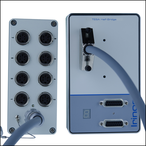
oUsing the type KF27, the measurement probes are connected via a separate connection box.
The definition of the type string is as follows:


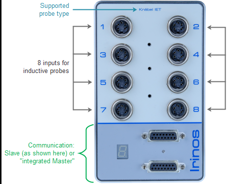
Connectors for "IR-TFV-8-x-M16-x" und "IR-TFV-8-x-M16IP-x"

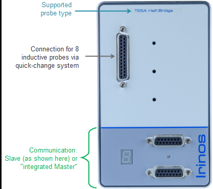
Connectors for "IR-TFV-8-x-KF27-x"

Irinos-Box IR-TFV with separate quick-change box
Connectors / elements
o8 inputs for inductive probes, directly connected (M16) or indirectly connected (KF27 / DSUB25).
oAn explanation of the communication section can be found in the general overview.
Sine oscillator / XSync oscillator synchronisation
Inductive probes require a sine signal. This is generated by the sine oscillator of the Irinos-Box. All measurement channels of an Irinos-Box have a common sine-oscillator. In order to get an accurate measurement value, the sine signal has no DC signal component.
In case of an overload of the sine-oscillator, e.g. when a probe is broken, the sine oscillator is automatically turned off. This event is signalled as followes:
oThe Status-LED flashes very fast (integrated Master).
oThe text "OSC" is displayed on the 7-digit display (Slave-Box).
oA default measurement value is used and the hardware status is set.
The Irinos-Box checks cyclically, if the short circuit is removed. If yes, the sine oscillator automatically restarts.
If the cabling situation is difficult, like for example in plug gauges, a phase shift between two sine oscillators could lead to signal interference, which may result in unstable measurement values.
Within an Irinos-System, all sine-oscillators are synchronized over all Irinos-Boxes. This is called the "XSync oscillator synchronisation" (patent pending). Thereby the Irinos system is also appropriate for difficult cabling situations.

IR-TFV ohne / mit XSync Oszillator-Synchronisation
Data acquisition
All measurement channels are sampled synchronously (no multiplexing).
The whole measurement signal is used (integrating measurement). This method has a much higher noise immunity than the widely used 1-point or 2-point sampling method. The filter, which is used for this method, is adjusted to the mechanical specification of the probe type.
In order to allow a quick exchange of the Irinos-Box by an identical type, all input channels are digitally pre-calibrated. The following table shows the value range:
Digital value |
Corresponding stroke for probe type Tesa halfbridge |
Corresponding stroke for probe type Knäbel IET |
|---|---|---|
- 32.000 |
- 2000 µm |
- 200 µm |
0 |
0 µm |
0 µm |
+32.000 |
+ 2000 µm |
+ 200 µm |
Connector type KF27 for quick-change system
If the quick-change system is used, it is possible to disconnect and connect all 8 channels via a single connector during operation of the system. This allows for example changing the measurement device without restarting the Irinos system.
