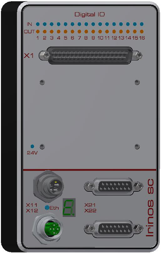
The Irinos SC-DIO box is designed to connect 16 digital inputs and 16 digital outputs. Connection is via a 37-pin D-sub connector. However, adaptors can be used to connect via terminal blocks or M23 connectors.
Power supply
In the SC-DIO-xxx-xx-xx-SYSP-xx variants, the Irinos system’s 24 V power supply is used to power the I/O. This reduces the system complexity, but does not allow the I/O power supply to be switched off separately.
For the SC-DIO-xxx-xx-xx-EXTP-xx variants, the 24V supply for the digital inputs/outputs must be supplied externally. For the DSUB37 variant, this is done via the DSUB connector; for the M23 adapter, a separate M12 connector is provided for this purpose; and for the terminal block adapter, the appropriate contacts are provided.
A blue LED indicates whether the 24 V power supply is present.
Only use a power supply unit that complies with protection class PELV for the power supply.
Note: It is possible to use 12 V DC as the input/output voltage. In this case, however, the status LED will not light up. The input/output LEDs will only glow dimly. The switching behaviour of the inputs/outputs remains unchanged.
Connector pinouts
DSUB37
➔ Connector type DSUB 37-pin, male
All digital inputs and outputs are connected via a single DSUB connector. The 24V power supply to the digital inputs is also provided via this connector (variant -EXTP).
If only the digital inputs are used, the 24V supply is not required. However, the reference ground (GND) must always be connected.
To achieve protection class IP65, suitable DSUB enclosures for the connector are required.
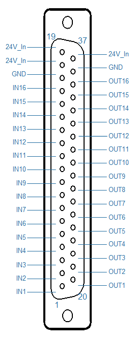
DSUB37 pin assignment for digital inputs/outputs
Pin |
Description |
Note |
Pin |
Description |
Note |
|---|---|---|---|---|---|
1 |
IN1 |
Input 1 |
20 |
OUT1 |
Output 1 |
2 |
IN2 |
Input 2 |
21 |
OUT2 |
Output 2 |
3 |
IN3 |
Input 3 |
22 |
OUT3 |
Output 3 |
4 |
IN4 |
Input 4 |
23 |
OUT4 |
Output 4 |
5 |
IN5 |
Input 5 |
24 |
OUT5 |
Output 5 |
6 |
IN6 |
Input 6 |
25 |
OUT6 |
Output 6 |
7 |
IN7 |
Input 7 |
26 |
OUT7 |
Output 7 |
8 |
IN8 |
Input 8 |
27 |
OUT8 |
Output 8 |
9 |
IN9 |
Input 9 |
28 |
OUT9 |
Output 9 |
10 |
IN10 |
Input 10 |
29 |
OUT10 |
Output 10 |
11 |
IN11 |
Input 11 |
30 |
OUT11 |
Output 11 |
12 |
IN12 |
Input 12 |
31 |
OUT12 |
Output 12 |
13 |
IN13 |
Input 13 |
32 |
OUT13 |
Output 13 |
14 |
IN14 |
Input 14 |
33 |
OUT14 |
Output 14 |
15 |
IN15 |
Input 15 |
34 |
OUT15 |
Output 15 |
16 |
IN16 |
Input 16 |
35 |
OUT16 |
Output 16 |
17 |
GND |
Reference ground for in-/outputs |
36 |
GND |
Reference ground for in-/outputs |
18 |
24V_In |
24V Power supply |
37 |
24V_In |
24V Power supply |
19 |
24V_In |
|
|
|
M23
➔ Connector type: M23 16-pol. female
There are 8 digital inputs and 8 digital outputs connected to each M23 connector.
A suitable mating connector is available, for example, from the manufacturer PhönixContact.
The M23 connectors are designed for connecting external connection modules, such as those available from various manufacturers (e.g. MurrElektronik, Turck, Weidmüller, PhönixContact, Escha).
Pre-assembled connection modules can be supplied on request as an addition to the Irinos system. Due to the wide variety of types available on the market, there is no standard module.
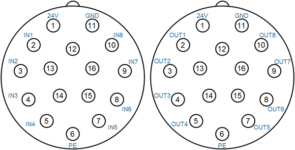
Pin configuration for M23 digital inputs/outputs
Pin |
Description |
Note |
|---|---|---|
1 |
24V |
24V Supplay |
2 |
IN1 / OUT1 |
Digital input/output 1 or 9 |
3 |
IN2 / OUT2 |
Digital input/output 2 or 10 |
4 |
IN3 / OUT3 |
Digital input/output 3 or 11 |
5 |
IN4 / OUT4 |
Digital input/output 4 or 12 |
6 |
PE |
Protective earth (applies only for type with separate supply SC-DIO-xx-xx-xx-EXTP-xx) |
7 |
IN5 / OUT5 |
Digital input/output 5 or 13 |
8 |
IN6 / OUT6 |
Digital input/output 6 or 14 |
9 |
IN7 / OUT7 |
Digital input/output 7 or 15 |
10 |
IN8 / OUT8 |
Digital input/output 8 or 16 |
11 |
GND |
Reference ground for digital I/O |
12 .. 16 |
- |
|
Power supply via M12 A-coded (M23 adaptor for -EXTP)
➔Connector type: M12 5-pin, A-coded
The digital inputs and outputs are powered via the M12 connector.
For the power supply, use only a power supply unit whose output voltage complies with protection class PELV!
Pre-assembled connection cables are available from various manufacturers, e.g. Phoenix Contact.
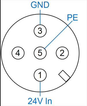
Pin assignment for power supply via M12
Pin |
Description |
Note |
|---|---|---|
1 |
24V In |
24V Input |
2 |
- |
|
3 |
GND |
Reference ground for digital I/Os |
4 |
- |
|
5 |
PE |
Protective earth |