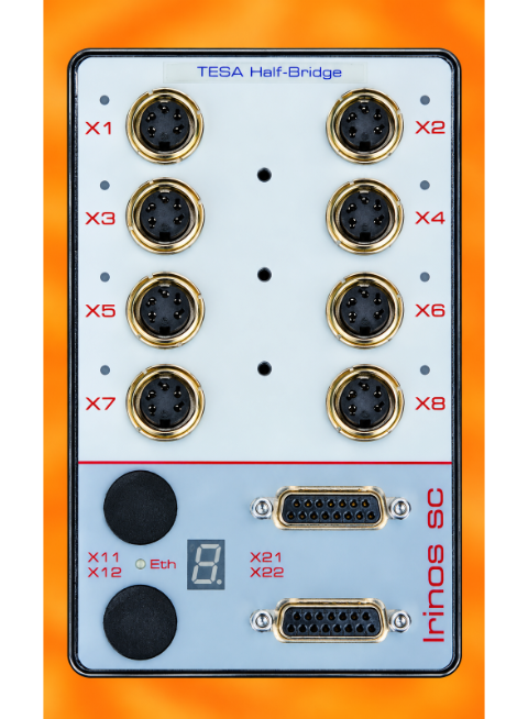
The Irinos SC-AIN box is suitable for connecting 8 analogue signals of ±10V.
Measurement
The analogue inputs are sampled synchronously internally (no multiplexing).
For technical reasons, they never produce exactly the same measured value for an identical input signal. To enable the input channel to be changed or the Irinos box to be swapped without any problems, the analogue inputs are digitally pre-calibrated at the factory. The calibration is carried out in such a way that, for an input signal of -10V, the measured value is -32,000; for 0V, the measured value is 0; and for +10V, the measured value is +32,000.
|
As the analogue inputs have very high impedance, the measured value may be ≠ 0 and fluctuate significantly when no input signal is connected. This is not a fault, but a technical consequence of the high-quality input characteristics. |

Connector pinout and connection instructions
➔Connector type M16 7-pin, female
Each connector has one analogue input of ±10V:
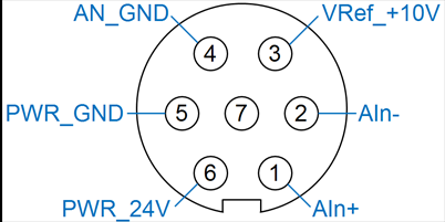
Pin configuration for analogue inputs ±10V
Pin |
Description |
Note |
|---|---|---|
1 |
Ain+ |
Positive pin of the differential analogue input. |
2 |
Ain- |
Negative pin of the differential analogue input. |
3 |
VRef_+10V |
+10 V reference voltage (output) |
4 |
AN_GND |
Reference ground for analogue input (Ain+ / Ain-) and reference voltage VRef_+10V. |
5 |
PWR_GND |
Reference ground for +24V power supply |
6 |
PWR_24V |
+24V power supply |
7 |
- |
|
Matching M16 mating connectors are available from various manufacturers, e.g. Binder.
Separation of the ground reference
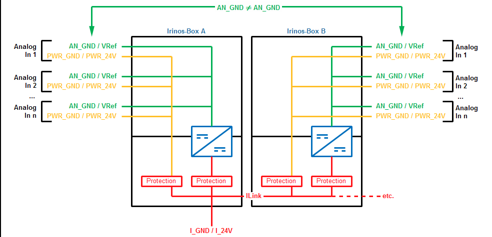
Just like the entire internal power supply of the Irinos box, the ground reference for the analogue signals (AN_GND) is also galvanically isolated from the SC-Link power supply (24V). Consequently, the analogue ground references of two Irinos boxes are also galvanically isolated from one another. However, all analogue inputs within an Irinos box share the same ground reference.
This isolation of the ground reference prevents the formation of ground loops, which frequently cause problems in practice. However, this requires the analogue signal sources to be correctly connected to the Irinos system.
Bezugsmasse der Analog-Eingänge
Connection of analogue signal sources
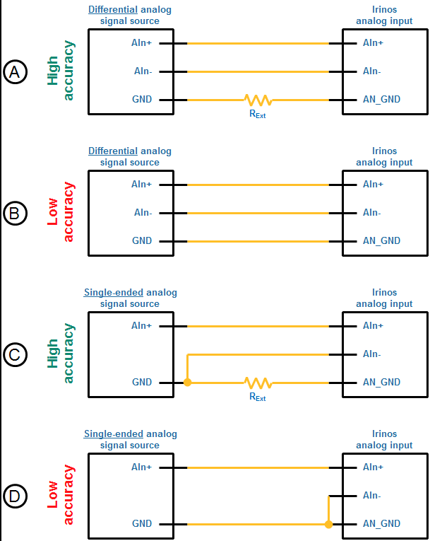
The following figure shows examples of how to connect analogue signal sources. As shown in the figure below, the analogue reference ground AN_GND of an Irinos box should not be connected directly to another reference ground. Connect them via a resistor RExt to ensure high measurement stability (figures A and C). The value of the resistor depends on the application. In most cases, a 1 kOhm resistor is appropriate.
For single-ended measurements, the AIn- input must be connected to the reference ground (GND) of the signal source. This connection should be made as close as possible to the signal source if the reference ground is isolated via the resistor RExt as recommended (figure B). Without the resistor, the connection should be made as close as possible to the Irinos box, e.g. at the connector (figure D).
Connection of analogue signal sources
Reference voltage VRef_+10V
A high-impedance measurement circuit can be supplied with a reference voltage via the VRef_+10V output. This is required, for example, when connecting measurement potentiometers (see the figure below).
Please note the maximum current rating for this reference voltage as specified in the data sheet.
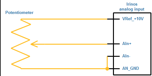
Connection example: ‘Potentiometer to analogue input’
24 outputs for powering analogue sensors
Each analogue input provides 24 V for powering analogue sensors, such as temperature transducers. This 24 V is drawn from the SC-Link power supply. Please refer to the datasheet for the maximum current rating.
The following figure shows an example connection for an analogue sensor powered via the Irinos system. As the reference potential of the analogue input (AN_GND) is isolated from the reference potential of the 24V supply, these must be connected to one another via an external resistor.
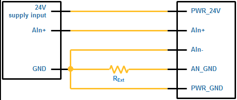
Connection example: ‘Analogue sensor to analogue input’