
Irinos Measurement System
➔ Connector type M16 7-pin, female
Each connector provides one analogue input ±10V:
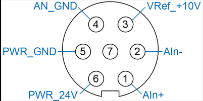
Connector for analogue inputs ±10V
Pin |
Description |
Note |
|---|---|---|
1 |
Ain+ |
Positive signal of the differential analogue input. |
2 |
Ain- |
Negative signal of the differential analogue input. |
3 |
VRef_+10V |
+10 V Reference voltage (output) |
4 |
AN_GND |
Ground for analogue input (Ain+ / Ain-) and reference input VRef_+10V. |
5 |
PWR_GND |
Ground for 24V sensor supply output |
6 |
PWR_24V |
24V sensor supply output |
7 |
- |
|
Isolation between ground potentials
The whole internal power supply of each Irinos-Box is galvanically isolated from the ILink power supply. This also covers the analogue ground AN_GND. Hence the analogue ground potentials of two Irinos-Boxes are also galvanically isolated. All analogue inputs of the same Irinos-Box have the same ground potential.
This separation of ground potentials prevents ground loops, which typically lead to measurement problems. Nonetheless it is important, that all signal sources are properly connected to the Irinos-System.
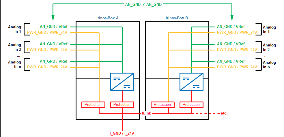
Ground potentials for analogue inputs
Connecting analogue signal sources
The following figure shows several examples for the connection of analogue signal sources. As shown, the analogue ground AN_GND should not be connected directly to any other ground potential. In order to achieve a high measurement stability, it is advised to use a resistor RExt (see A and C). The resistance value depends on the application. Typically a 1 kOhm resistor is appropriate.
For single-ended measurements, the input AIn- must be connected to the ground potential GND of the signal source. This connection should be made next to the signal source, if the ground potentials are connected via a resistor as depicted above (see B). Without this resistor, the connection should be made next to the Irinos-Box, e.g. inside the connector (see D).
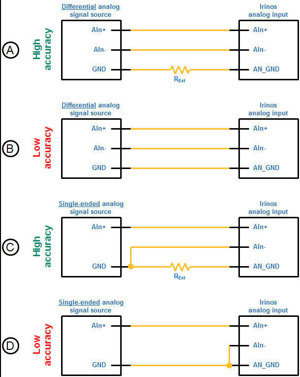
Connecting analogue signal sources
Output VRef_+10V
The output VRef_+10V can be used as a reference voltage for a high-impedance measurement circuit. This is for example required for the connection of measurement potentiometers.
Please observe the maximum output power for the reference voltage. It can be found in the datasheet.
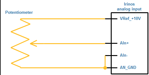
Example: connecting a potentiometer to an analogue input
24 supply for analogue sensors
For the supply of analogue sensors, e.g. temperature transducers, 24V are available at each output connector. These are taken from the ILink power supply. The maximum load is defined in the datasheet.
The following figure shows an example for the supply of an analogue sensor via the Irinos-System. Since the analogue ground AN_GND and the ILink supply ground PWR_GND are isolated, these must be connected via an external resistor.
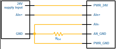
Example for the connection of an analogue sensor
