For the simplest applications, the Irinos SC offers an ASCII-based text interface. This is comparable to the RS232 connection to measurement hardware that was commonly used in the past.
The ASCII interface can be accessed either via TCP or via UDP. Whilst the ASCII protocol itself is identical, the two options differ as follows:
|
TCP |
UDP |
Port number |
TCP 22515 |
UDP 22515 |
Packet loss |
In the event of a packet loss, automatic retransmission of data at the protocol level (TCP). |
If packets are lost at the UDP level, the data exchange must be repeated manually. |
Latency |
In theory, very long latency is possible. In practice, however, this is negligible with a 1:1 Ethernet connection. |
Very low latency is possible. |
Max text length |
16000 characters/bytes |
1450 characters/bytes with 1:1 ethernet connection |
Data is always exchanged using a question-and-answer procedure; that is, the measurement software sends a request to the Irinos system, which then sends a response. Each request/response consists of a sort of ‘header’, the actual data, and an end marker.
The header allows different commands to be distinguished on the basis of an identifier. The data that follows is optional, depending on the question or answer. The end marker is terminated by a “Carriage Return (CR)” and a “Line Feed (LF)”, and is represented below as {CRLF}. CR has the ASCII code 0x0D and LF has the ASCII code 0x0A.
Note: The Irinos system also recognises either CR alone or LF alone as an end, but always returns both in the response.
The protocol is explained using the following examples:
Command |
Request |
Response |
Comments |
Dummy command |
?Nop1{CRLF} |
=Nop1#OK{CRLF} |
Useful for testing communication and as a ‘heartbeat’. |
Read measurement values |
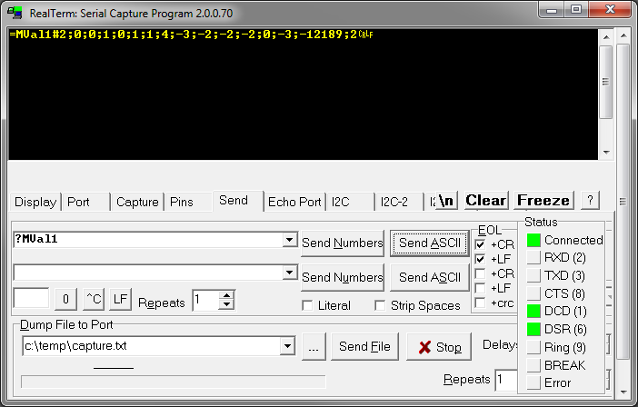
?MVal1{CRLF} |
=MVal1#0;-3;-12189;2{CRLF} |
Example for 4 measurement channels. If there are more measurement channels, the answer will be correspondingly longer. |
Read digital inputs |
?DIn1{CRLF} |
=DIn1#0;1;0;1;1;0;0;0;0;0;0;1;0;1;0;1{CRLF} |
Example of 16 digital inputs. Values can be 0 or 1. |
Write digital outputs |
?DOutSet1#1;1;0;0;1;0;0;0;0;0;0;0;1;1;1;1{CRLF} |
=DOutSet1#1;1;0;0;1;0;0;0;0;0;0;0;1;1;1;1{CRLF} |
The response returns the current status of all digital outputs. There may be more of these than were specified in the request if only some of the outputs were set in the request. Values can be 0 or 1. |
Read measurement values and digital inputs together |
?MValDIn1{CRLF} |
=MValDIn1#0;-3;-12189;2;0;1;0;1;1;0;0;0;0;0;0;1;0;1;0;1{CRLF} |
A combination of ‘MVal1’ and ‘DIn1’. The measured values come first, followed by the digital inputs. |
|
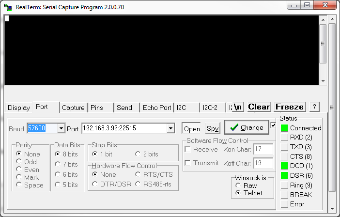
Tip: For testing purposes, data can also be exchanged using a range of standard terminal programs, such as ‘RealTerm’.
|