Irinos Measurement System
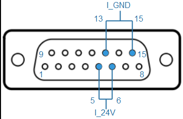
➔ Connector type: DSUB 15-pin female
The ILink interface combines wires for the power supply and the communication between the Irinos-Boxes in a single cable / connector. For proper operation of the Irinos-System, it is important to use high quality ILink cables with specific electrical specifications. Therefore only original cables of the type IR-ILINK must be used.
By using an appropriate housing for the cable connectors, protection class IP65 can be reached. Therefore the ILink cables are available as a standard type and as a IP65 type.
Power to the Irinos-System is supplied via the ILink interface. All other pins must remain unconnected, since this could lead to reflections, which can interrupt the data transfer between the Irinos-Boxes.

Power supply via ILink interface
Pin |
Description |
Note |
|---|---|---|
1 |
IL_Data1 |
Data 1 |
2 |
IL_GND |
Ground potential for data lines |
3 |
IL_Data2 |
Data 2 |
4 |
- |
|
5 |
I_24V |
24 V – power supply for the Irinos-System. |
6 |
I_24V |
24 V – power supply for the Irinos-System. |
7 |
IL_Data3 |
Data 3 |
8 |
IStat |
Detection signal |
9 |
IL_Data4 |
Data 4 |
10 |
- |
|
11 |
IL_Data5 |
Data 5 |
12 |
- |
|
13 |
I_GND |
Ground potential for the power supply of the Irinos-System. |
14 |
IL_Data6 |
Data 6 |
15 |
I_GND |
Ground potential for the power supply of the Irinos-System. |
The pinning of the ILink connector has been chosen to avoid any damage of incremental encoders with standard pinning, if they are plugged into the ILink interface. For encoders with special pinning, this may be different.
The communication of the ILink interface is based on a bus system, which must be terminated by a termination resistor at both ends. This termination is switched on automatically: the Irinos-System detects the first and the last Irinos-Box and enables their termination resistors. This is signalled via the termination LED between the ILink connectors.
An exception are the Irinos power supplies IR-PU. If it is placed at the beginning or the end of the ILink cabling, the cable length to the next Irinos-Box must not exceed 0,3m.
